Automation system of industrial control
Posted on 2019 / 12 / 09 in ChSU
Warm greetings to you all in this little blog article, which is described some parameters of automation systems and methods of nondestructive control in industry. Some automation examples in mineral fertilizer industry will also be considered.
This short article represents a little translation of more detailed Russian version of it. Time after time I will try to add more details and practice examples in this paper.
Moreover, I will be very grateful for any reviews and opinions about this theme and my style of writing. Please, do not hesitate to contact me with e-mails (Dm.Yunovidov@gmail.com) or comment button below.
So, shall we start?
Table of content
- Introduction
- Architecture of automation system in Industry
- Base characteristics of measurement systems
- Temperature measurement
- Pressure and force measurement
- Displacement and velocity measurement
- Flow measurement
- Level, humidity and pH measurement
- Signal conditioning circuits
- Conclusion
1. Introduction
1.1 Intro and objectives
In this part of the article some main principles and determination in automation is presented. By the end of the chapter I'd like you to understand:
- definition of automation, control and information technology (IT);
- connection between such things;
- conception of 'products life cycle' and role of automation in it;
- classification of industry facilities and automation system.
1.2 Engineer science and terminology
The engineer science is the discrete discipline with its own language, tasks and instruments (as well, as the other science like art, social, natural science, etc.). The main question for engineer is:
how can I solve this problem?
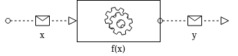
Such question lead us to the typical engineer definition of system as the black box (we do not know what inside, and it did not bother us, what is important - how we put it in work). The main subjects for us are input and output flow of this black box and how this flows relay to each other. It is very similar to programming. Each devise will give direct output from concrete input (fig. 1.1).
|
Fig. 1.1. The black box concept. |
The other important feature of engineer science are special instruments (mainly for the visualization):
- technical draws and specifications;
- schemes;
- block diagrams and programs;
- technical and principal papers, etc..
I think, that you already know it and see it a lot...
Control, automation, robotization and sensors are the most important things for modern industry. Especially it is relevant for Industry 4.0 - yet another industry revolutions, which are newer stop (and it is amazing)! So, us you can see, the automation is always actual (beginning from the 18th century and uncle Ford).
Main problems of automation and control relay to mechanical system, automatic perception, navigation and design making system.
The separate problem is 'chaos' systems interpretation, which include a lot of non-linear dynamic systems. In spite of linear dynamic systems (which we can interpret with differential equations), the 'chaotic' dynamic system highly sensitive for external conditions and variations of system parameters. For such system interpretation widely use statistical methods: nonlinear multidimensional analysis, machine learning and other 'big data analysis'. But, it is not the theme of this little course.
We study automation system classification and the control, which is broadly speaking a simple check between set (desire) and real parameters in different industrial process. And when we see one, we say about defect in process or product. The process of search of defects itself name diagnostics.
For this purpose widely use a non-destructive methods of control: visual (color, odor, shape, etc.), spectrophotometry (UV, Infrared, visible light or X-ray), ultrasound analysis, etc. But all of this complicated and hard-to-speak methods are based on sensors.
All of these sensors and methods of control are used for acquire information. There are a lot of date there, and we swim in big sea of different data, which we can use for control and diagnostics. Well, we are ourselves are data, which we can't calculate properly.
Analyzed parameters (parameters of diagnostics) of object contain information about object condition and there are 3 types:
-
functional parameters of product - which characterize the exploitation of the product (maximum force, liquid pressure, acceleration/deceleration time, specific energy consumption, ets.);
-
structure parameters - which directly characterize the condition of specific part of the product (element position coordinates, corrosion, etc.);
-
associated process parameters - defined from external conditions and the processes which accompany a product (temperature, vibration, acoustic signals, level and a spectrum of noises, an error of processing, etc.) - are more widespread, our stop.
The control results are usually presented in the form of continuous functions from time (\(K_J(t)\)) with indication of permissible deviations (errors). The concept of sensitivity of the diagnostic parameter (\(K\)) to the state parameter (\(Q\)) is also important: \(\frac{dK}{dQ}\).
Task. Let's think how we can 'see' the sensitivity? Plot the figure \(K_J(t) = aQ_J(t) + b\) (with random selected a, b and other parameters) and find the sensitivity.
There are also some type of control: hardware, software, manual or automated, specialized or universal. The very beginning of the concept of non-destructive testing and diagnostics usually refers to the time of X-rays discovery (November 1895), which allowed to detect a bones under the skin and metal object in a closed wooden box.
The accuracy of control system depends on the sensitivity and resolution of its components (incoming information channels) and the accuracy of statistical calculation (and algorithms). In addition, it depends on the calibration (the quality of used reference samples).
Furthermore, operator functions (peoples work) in many systems are main part of the process control and too complex for automation, and decision-making systems have not yet become widespread.
Thus, there are four important directions of development of automated control methods:
-
Training of methods and tools of analysis (intellectualize), as well as search for quality metrics.
-
Development of the unified system of quality control (standardization).
-
Improvement of diagnostics (hardware and software).
-
Standardization and implementation of control systems in the field (regulatory documentation).
The main idea of this article is research the 3rd part of this list. But for now, we concentrate about classification and terminology.
First of all, each system of control build on measuring - it is process of quantity determination in special units (and we need to compare it with something).
The industry - systematic activity that could be related to manufacture, service or trade (for this article we certainly use manufacture).
Automation - a set of technologies that provide the operation of machines and systems without significant human intervention (with some performance compare to manual operation).
Management and Control - a set of technologies that achieves desired outputs from set input for systems and machines.
Sensors - devices that provide information about process by measure, count, track, etc.
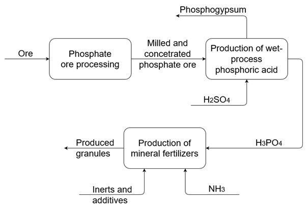
In this article we will mainly focus on the general concepts of automation in today's industry and next, try to understand some instrumentation implementation of non-destructive testing. My area of professional activity includes providing control in the production of mineral fertilizers, and I will try to give more concrete examples from this industrial area (Fig. 1.2).
|
Fig. 1.2. Structure of mineral fertilizer production. |
Task. For better understanding of terminology, try to explain all previous given statements (industry, automation, management and control and sensors) with your own example (like, in case of temperature control in ceramic furnace).
From the other hand, it is highly important to understand differences in automation system and control system:
-
Automation Systems may include Control Systems but the reverse is not true.
-
The main function of control systems is to ensure that outputs follow the set input (in number of set points). However, automation systems may have much more functionality (such as computing set points, monitoring, startup or shutdown the process, scheduling etc).
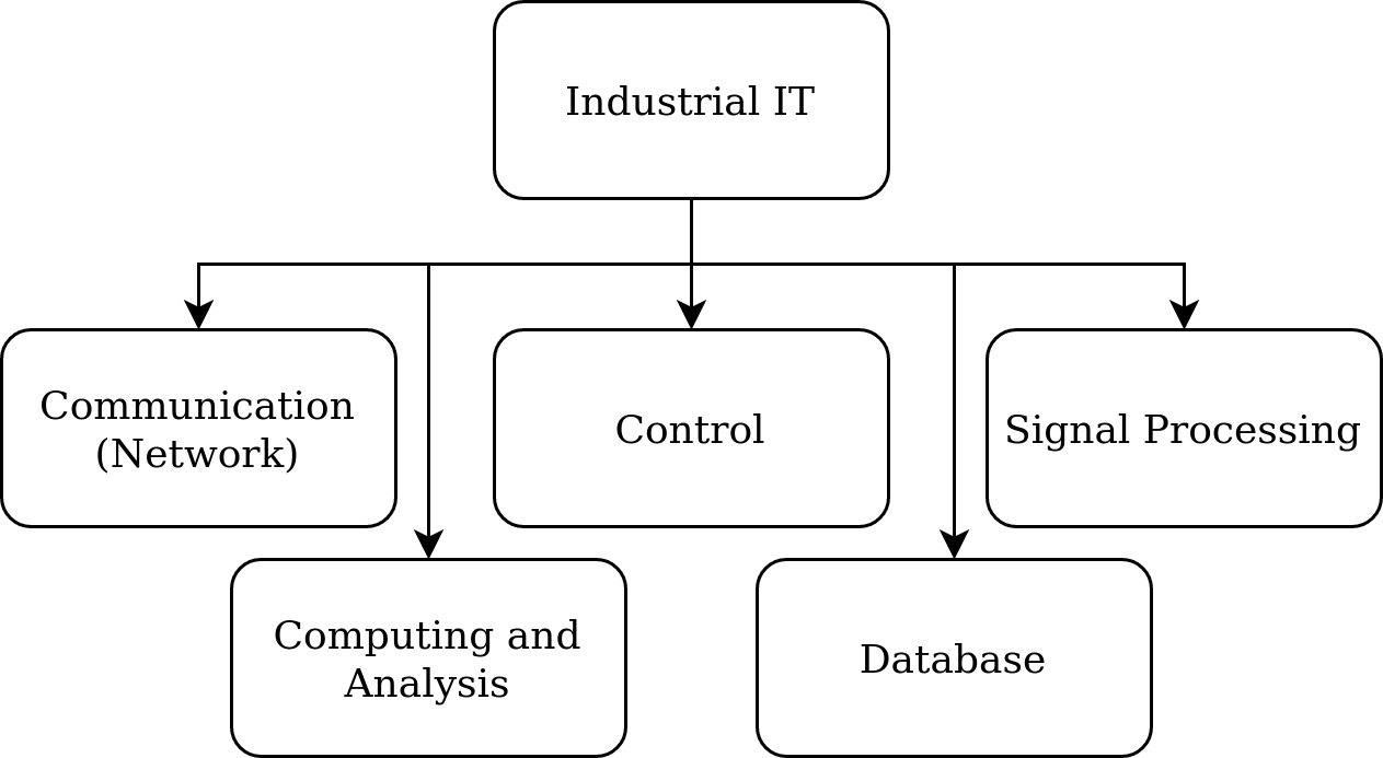
Furthermore, industrial automation systems makes extensive use of information technology (IT, Fig. 1.3). In the contrary, control system use IT much less.
|
Fig. 1.3. Major areas of IT in industrial automation systems. |
Task. Try to find an practical example of using IT in automated system (Hint: Try using the internet)
However, industrial automation systems are different from IT:
- Industrial automation systems involves a significant number of hardware technologies (instruments, sensors, motors, circuits for signal processing, etc.).
- Low level automation systems use IT much less, working more with hardware, electronics and embedded computing (e.g. sensors and actuators).
1.3 Role and types of automation in industry
It is generally assumed that the main goals of using automation in industry are:
- Reduction of manual control (minimization of error due to human factor);
- increase of the economic effect of production (... profit).
The economic effect itself may express as:
Automation affects to the ratio of cost/unit (decrease the cost) and to the price/unit (increase the quantity). Thus, automation affects the economy from a position:
- of scale (economy of scale) - reduction of costs per unit of production (because automation increase production volume and operational and time efficiency);
- of objective (application, economy of scope) - when automation can provide ability to produce a wider range of products.
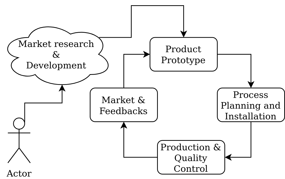
Typical product life cycle is shown in Fig. 1.4.
|
Fig. 1.4. Typical life cycle of the product. |
At the first stage the idea of products is created on the base of research of the market, demands and assets. Then a manufacturing model is created, and the prototype of the product is made. After checking the performance and suitability of the prototype, the production is scaled up and assembled to ensure that the necessary resources and technologies are available for mass production. Next, direct mass production and product quality control are carried out. The produced product enters the market, from which comes the corresponding response (feedback); on the basis of which the production evolves (increases capacity or changes the product).
Task. Where can automation be used in this scheme and what advantages it provide?
Tasks. Give examples of industries: where 1 - economy of scale is more important than economy of scope; 2 - the opposite and 3 - they are equal.
1.3.1 Type of production systems
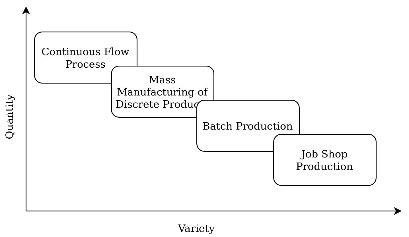
Based on the previous determined scale and scope we can determine major type of production (fig. 1.5).
|
Fig. 1.5. Classification of production system. |
-
Continuous flow process - the product produced "continuously" (it is not a discrete object). Volumes are large, the difference in products is relatively small (oil refining, cement production, steel industry, etc.).
-
Mass manufacturing of discrete production - large volumes of discrete objects, variation of products is rather limited (instrument making, automotive, frying pans production, etc.).
-
Series production (batch production) - produces a series of discrete or continuous products, differences between products are bigger then in previous one. The same set of equipment produces many types of products (but for each series/party a separate parameters are set - it is "recipe" of the batch) (pharmaceuticals, foundry, plastic molding, printing, etc.). This type also includes the production of mineral fertilizers (although for some technological schemes and facilities we can assume the mass production of discrete products).
-
Job shops (workshops) - a small number of discrete products, usually to order, any changes in the product are possible (prototyping, 3D printing, various workshops, etc.).
1.3.2 Type of automation system
Automatic systems can be categorized according to the flexibility and degree of integration into the manufacturing process.
-
Fixed automation - a fixed set of operating parameters for mechanized equipment. It is used to perform fixed and repetitive operations in order to produce more identical parts (used in continuous and mass production types, e.g.: paint shop conveyors, distillation, sample feed lines, etc.).
-
Programmable automation - change of operation sequence and configuration of machines by electronic controls. This scheme may require non-trivial programming (e.g. for different PLCs, usually used in batch production where the variety of working equipment is low and the variation of products is high; e.g. paper or steel mills, etc.).
-
Flexible automation - used in flexible manufacturing systems (FMS) that are constantly controlled by the computer (operators enter high level commands and lower level changes are made automatically; usually implement in batch and job shop production where there are many varieties of product and the workload varies from medium to low). Such systems usually use multipurpose computers with numerical control (CNC), automobiles with automatic guidance (AGV, robotic systems) and others.
-
Integrated automation - complete automation of production where all processes are performed and coordinated by computer (Computer Integrated Manufacturing - CIM). In other words, it is full integration of technological and management operations using IT. Often it can also include a business management system too. So far, successful examples of such systems are very small, and it is difficult to examine it (according to type of production).
Note that the scale and complexity of automated systems is growing from fixed to integrated automation. But remember that the type of automation must be chosen for each particular production and task (and investments in it must be justified economically).
For example, fixed automation is appropriate when:
- The differences in product type are small (size, shape, number of parts, material).
- There is a predictable and stable demand for a product within 2-5 years (and the production capacity is also stable).
- The production volume per time is high.
- Optimum productivity due to competition is required.
Flexible automation, on the other hand, is used in the following situations:
- There are significant differences in product types (for one production system).
- The product model life cycle is small (frequent improvements and design modifications that change production is required).
- Production volumes are moderate and market demand is not so predictable.
Nevertheless, within the framework of nowadays industrial revolve 'Industry 4.0', productions are increasingly inclined to use serial production and to upgrade continuous and mass production for these purposes. As a result, flexible automation is becoming more and more popular.
Tasks. How we can determine which type of automation prevails in manufactures due to a technical inspection of it? For which factory would you recommend computer integrated manufacturing and why? Which type of automation would you recommend for production:
- incandescent bulbs;
- clothes;
- textiles;
- mineral fertilizers;
- printing;
- pharmaceuticals;
- toys.
1.4 Exercises
-
Describe the role of automation in the overall profitability of the production system.
-
How does industrial automation help to save money and what types of savings it is?
-
Enter the query "automation history" on the Internet and read the links you like.
-
Study ISO 9001 "Quality management systems". Which main criteria of quality management system you can find?
-
What are the alternative definitions for industry, automation and control?
2. Architecture of automation system in Industry
2.1 Intro & objections
In this section we try to understand main structure of automation control in industry. For the end of the section I wish you can:
- show elements of industrial automation systems and its structure (levels of organization);
- describe of connection between levels of organization (as well as name main technology of it);
- give industrial examples for each of described levels;
- can describe information flow between levels.
2.2 Architecture of automation system in Industry
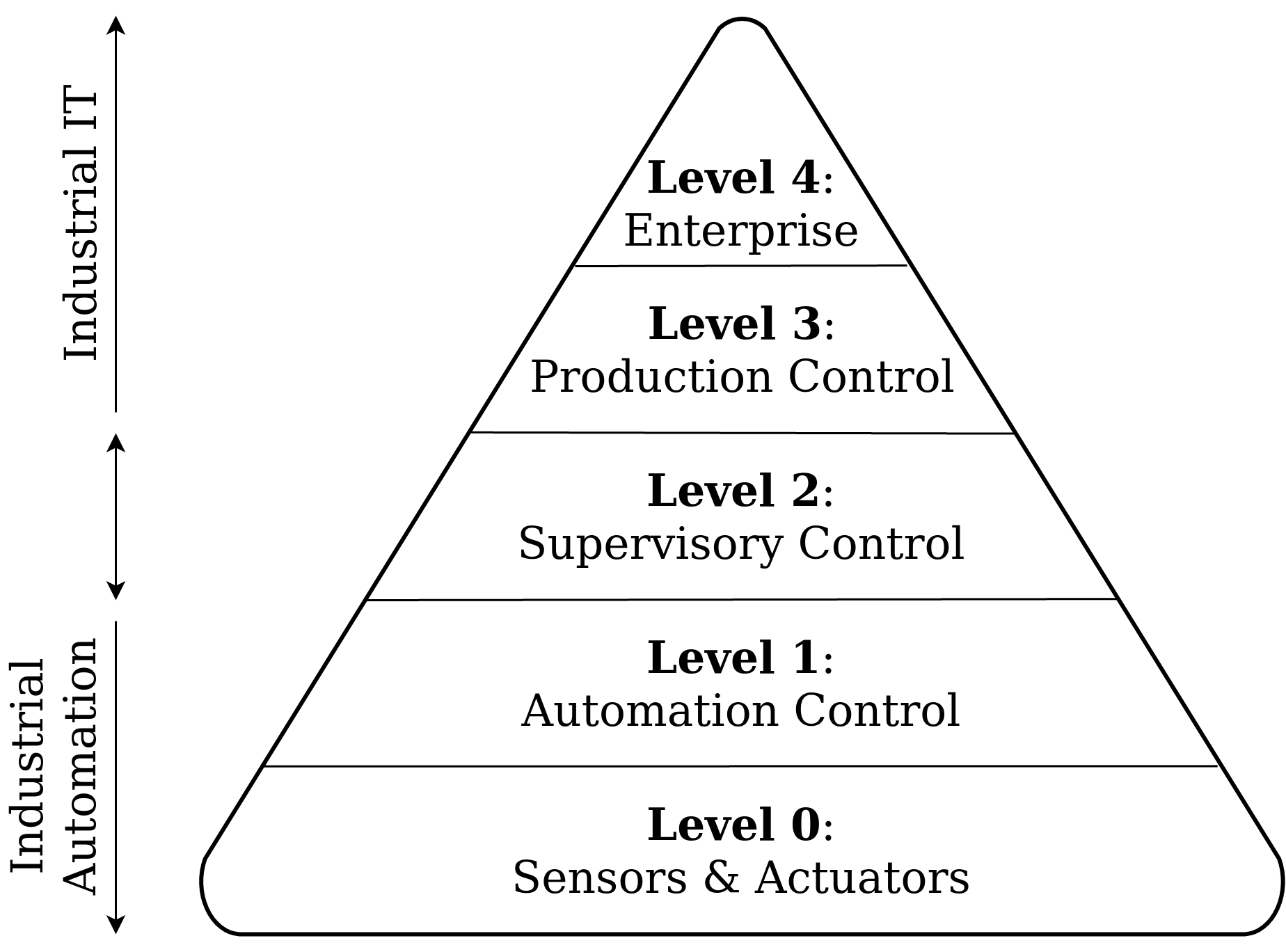
Let's view the structure of typical industries (fig. 2.1) and try to understand our place in it. Just image one of the typical facilities (JSC "Horns and Hooves" for example).
|
Fig. 2.1. Architecture of industry production. Pay attention for level markers. |
The management (or product enterprise system) is placed on the 4th level (the upper one). This level include determined of economical, usability and other 'high-level' features of production and product. And it is not where we implement automation yet.
The next level is quality control of produced product (level 3) where it compares with regulatory documentations. It's also done while people do it.
The supervisory control is on the 2nd level. We can say that this level connect people command with machinery instruction. This function is taken over by production operators together with the automatic process control system (room with large monitors in the factory). This level is also called an 'supervisory control and data acquisition' (SCADA) system.
Systems of automatic control, more precisely, systems of maintenance of the set parameters of quality (which are set by the control system and operators in level 2) occupy level 1. At this level, computers or logic controllers are often used. The automation by itself.
At the last, 0 level, there are sensors and actuators - devices for receiving and transmitting physical information about the process, which they provide to higher control levels.
Interaction between levels is provided by the integrated information-communication system of the plant or SCADA (for JSC "Apatit" it is the 'PI System').
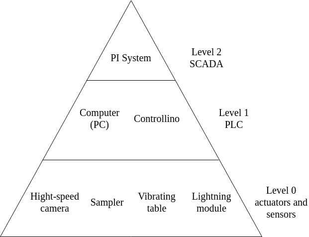
Nowadays, robotic control systems are widespread (the system of 0 - 2 levels, interacting directly with the SCADA). Some example of the level communication in such system are shown on the fig. 2.2.
|
Fig. 2.2. Architecture of robotic system of granules size control in the mineral fertilizer facility. |
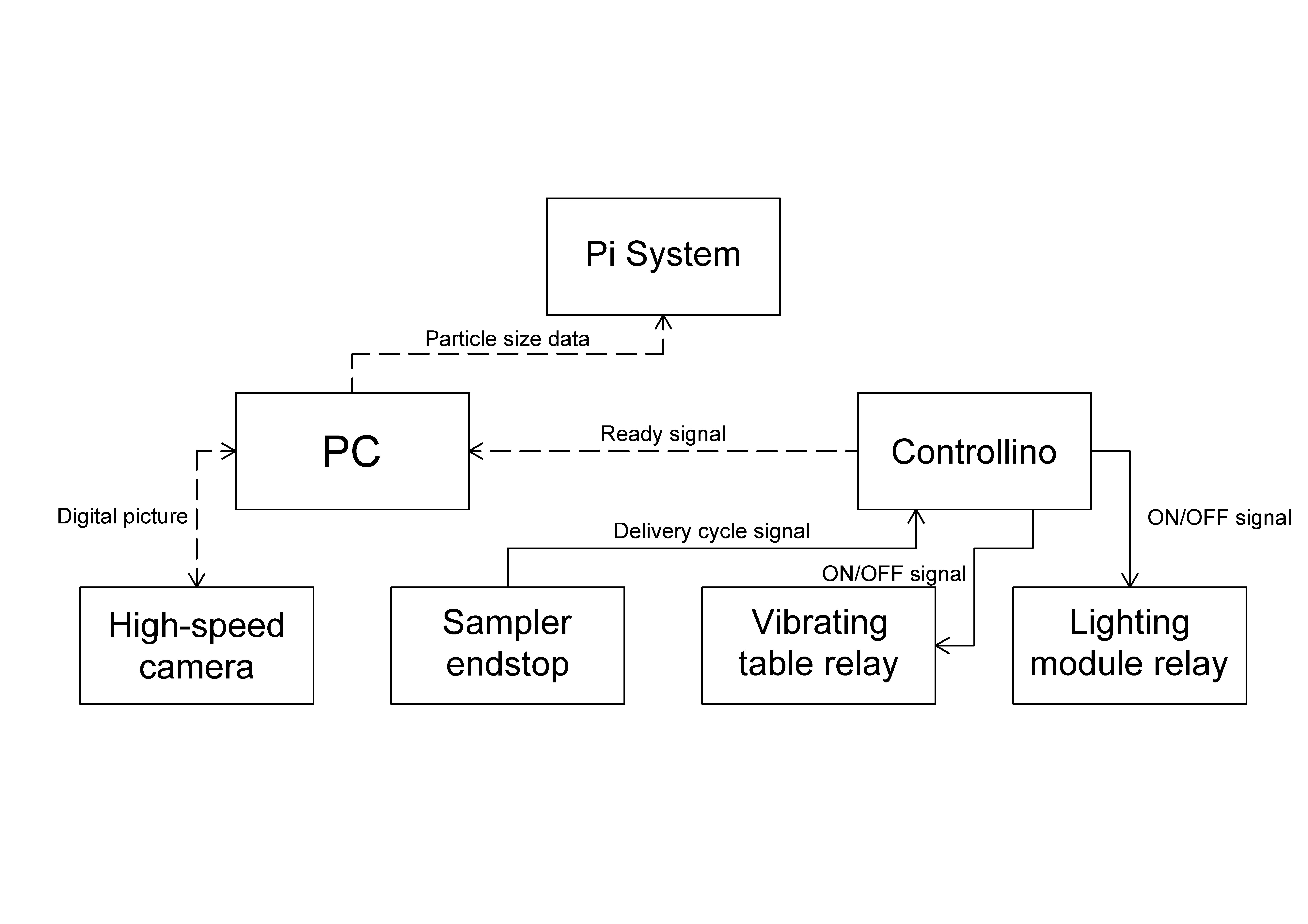
This system was developed by me and my colleagues and is used to control the particle size distribution. A more detailed worked principle and signals are shown in Fig. 2.3.
|
Fig. 2.3. Signal and data flows for a robotic control system of particle size distribution. Dotted lines represent digital signals, the others represent analogue signals. |
Note that the decision-making time and the amount of information embedded in a particular decision increases from 0 to 4 levels. In other words, the higher the level - the more common control terms are used (which means that it takes time and experience/database to decode them). Managers speak "make quality for the market"; the technical department transfers "make quality according to standard ISO 2х2"; quality management carry out analyses and transfer parameters to operators; they give commands to control system/facilities personal "to twist handles 1-2-3 in positions 3-2-1"; automatic control system (with the help of facilities personal) "twists the handles and keeps set parameters"; sensors and actuators "spin, measure and rumble" with transferring new information backwards. Something like that.
At first glance, our place is on the 0 and 1 levels of this system. However, the automation often include the 2nd level too (see the note about robotic systems, Fig. 2.2). However, this short article review the basic principle of it.
2.3 Level 0. Sensors and Actuators
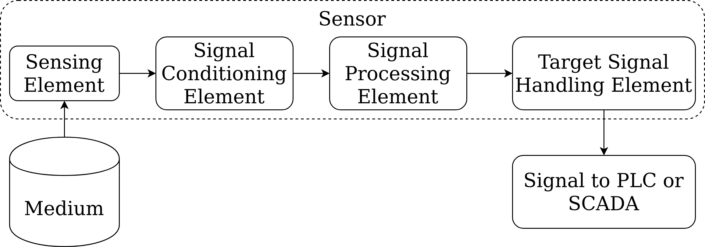
The first control system is the sensor system (level 0, which is directly responsible for automation). It should give us accurate and sensitive information (signal) related to a physical value (e.g. temperature) (Figure 2.4). Special devices are responsible for that - sensors (gages). All this is necessary to make the required calculations at level 2 and to produce the new input (set new value) for technological process within the framework (to ensure, that overall quality if belong to ISO). The signal from/to level 0 is transmitted in the form of electric or pneumatic information and further is converted into an input parameter of the technological process if needed (heat, force, etc.). Thus, the functions of the sensor is to transmit the process signal and the functions of actuator is to receive the control signal and change the technological process.
|
Fig. 2.4. Sensors system (level 0). |
sensing element - an element, whose physical/chemical/biological properties depend on the physical environment (direct or indirect contact). A typical example is the change in resistivity due to the heating of a resistance temperature detector (RTD).
Next comes the signal conditioning module (signal-conditioning element) which changes the character of the signal from the sensor (usually to electrical form: voltage, current, capacitance or inductance). This transformation depends mainly on the sensor (hence, this element is specific to the type of sensor). For example, for an RTD, a resistance change can be easily converted to voltage by including the RTD in Wheatstone's bridge. Therefore, the bridge serves as a signal conditioning module. Such module can also be used for special functions not related to signal conversion (e.g. "ambient referencing" of thermocouples). Typically, analogue electronic circuits are used for these modules, which eventually produce electrical signals in the form of voltage or current over specific ranges.
The following module is the signal processing element, which is used to handle the electrical signal (generated by the first cascade) for filtration (noise elimination), diagnostics (sensor evaluation), linearisation (output linearly associated with the physical parameters of the medium), etc.. Therefore, the signal processing elements are usually more general in purpose.
The last module, the target signal-handling element, is usually universal too. It can perform various functions: data/signal display, recording, storage, process control feedback, etc.. Examples are temperature chart recorder, instrumentation tape recorder, digital display or analog-to-digital converter (ADC) etc.
Modern sensors also typically have the ability to digitally transmit data using serial, parallel or network protocols (RS 432, USB, Ethernet, etc.). These sensors are called "smart" and contain the embedded digital electronic signal processing circuits.
So, make the conclusion, the sensor converts physical signals (temperature, pressure, speed, etc.) into electrical or pneumatic forms of information, forming our input signals for hight level systems. But in order to make the control action (or implement the control signal), we need to convert it back to physical form. To do this we use actuator system (we are still at level 0).
These systems characterize the response of the devices, depending on the sensory signal received and the set points from higher levels (such as level 1 or 2).
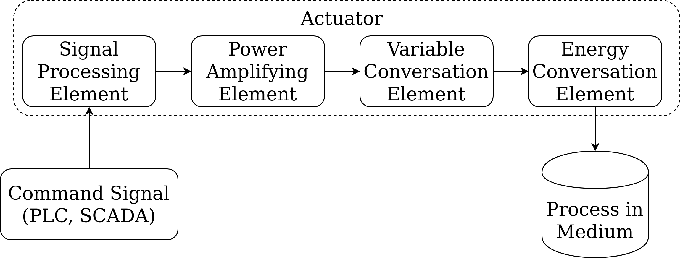
Actuator - The switch of the logic signal to the physical signal. This systems are required to control production process (e.g. by regulating flows, product mass, etc.). Once again, these are systems, which inverse to sensors (actuators catch control signal, which is usually weak voltage and current and convert it). There are two ways to do such transformation. First, an actuator can convert a weak current into a physical phenomenon (torque, heat, flow). Secondly, it can amplify the energy of an incoming electrical signal and this signal can directly influence the production process. Thus, sensors and actuators are different devices: actuators are power devices, while sensors are mostly work with low current. Actuators are usually more energy-intensive and in most cases produces a movement (which is then converted into other forms of physical action). Nevertheless, the logic of work of actuators approximately corresponds to sensors (fig. 2.5). Similar to sensors, there are "smart actuators".
a) 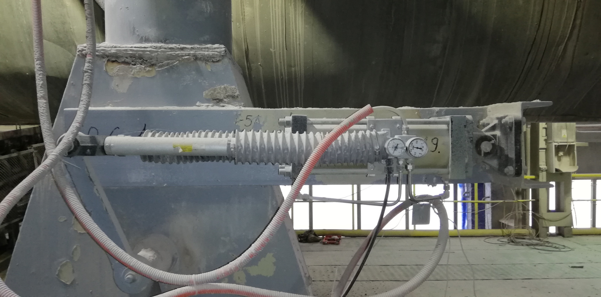
b) |
Рис. 2.5. Main configuration of actuator system (a) and example of it industrial implementation (b). |
The signal processing element receives the command from the control system in electric form. This command can be processed in several ways. For example, filtering (to remove an incoming signal of a certain frequency, which may cause resonance) or amplification can be performed. Many actuators are closed loop control units with feedback (to ensure accurate triggering), and for this reason, the electronic signal processing module often contains the control system for the drive itself.
Next, the power amplifying element sometimes contains linear power amplification stages called "servo amplifiers". In other cases, it may consist of motor power electronic circuits (for example, for motor driven actuators).
Variable conversion element performs the function of changing the nature of the signal generated by the electronic power amplification element (from electric to non-electrical form, usually in motion). Examples are hydroelectrically servo valves, stepper/servo motors, Current to Pneumatic Pressure converters, etc.
Energy conversion element which generally includes non-electrical power conversion elements are used to further increase power (usually by hydraulic or pneumatic mechanisms). Non-electrical variable conversion elements can then be used to convert a controlled variable to the desired form, often in several stages. Typical examples include conversion of movement to flow rate (flow valves), rotary to linear movement, flow rate to heat (using steam or hot liquids), etc.
Finally, actuators can be equipped with various supporting elements for lubrication/cooling/filtration, tanks, feedback sensors, display components, remote control as well as safety mechanisms and etc.
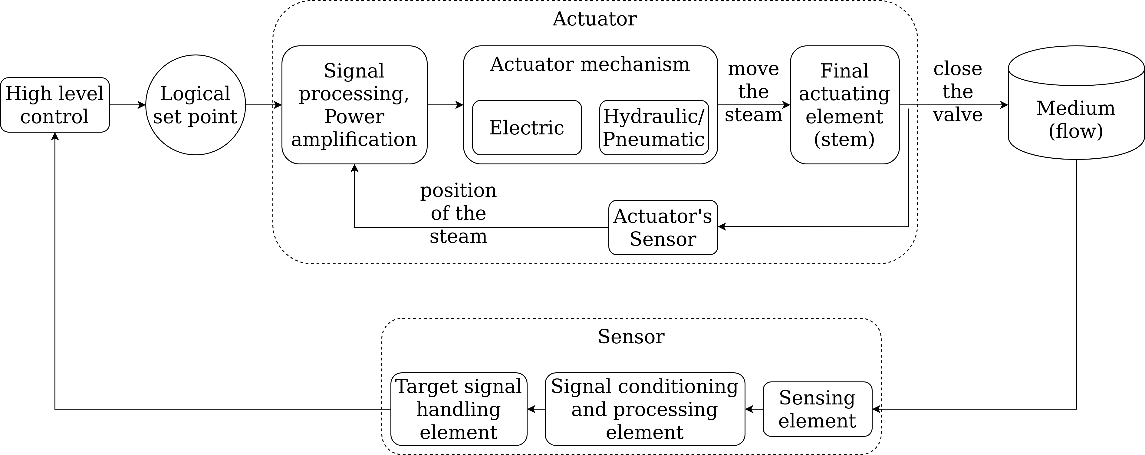
Summing up this section, level 0 systems can be displayed in general terms by an example of steam valve control (Fig. 2.6).
|
Fig. 2.6. Level 0 control system. |
2.4 Level 1. System of automation control
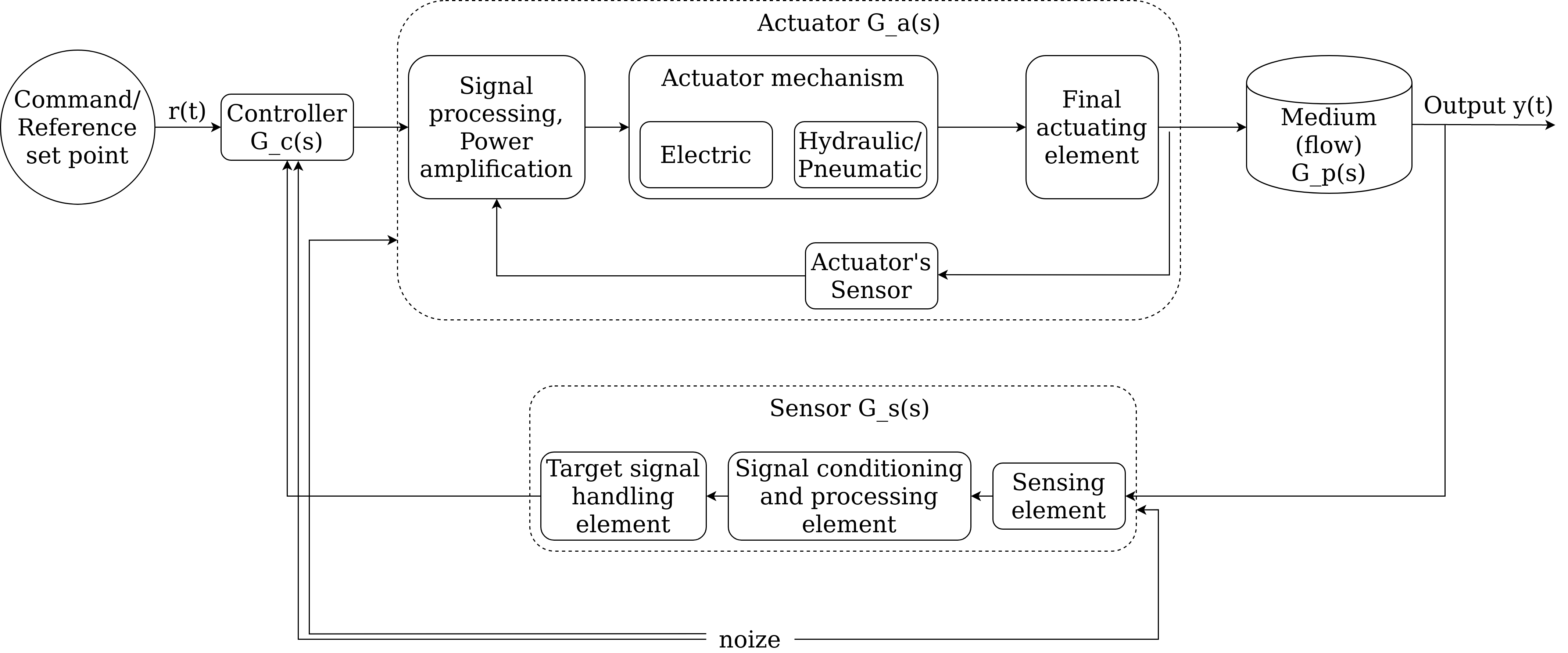
Now we have the opportunity to go up to a higher level and consider the automatic control system (level 1). By such industrial control systems we mean the use of controller. This is a new element (usually electronic or pneumatic), which receives signals from operators (SCADA) and feedback from the industrial process (sensor), and sent new outputs signals for actuators (Fig. 2.7).
|
Fig. 2.7. Loop of automation control system (level 1). |
This loop is also often called Automatic Control, Process Control, Feedback Control, etc. In this case, the purpose of the controller is to provide such input signals to the actuator, that the output signal (process parameter y(t)) follows the operator command r(t) as close as possible (both in value and time). Fig. 2.7 shows the general structure of the control loop with its components: the controller, drive, sensor and the process itself (the environment in which the process takes place). In addition, the signals are marked (existing at different points of the system). Described action include two main steps: a command (set point or reference signal) and external interference (noise).
Difficulties in achieving the set point are due to internal unavoidable noise (changing loads, induced currents, sensor noise) and external production factors (instability, uncertainty and variability in process dynamics).
Once again, pay attention to the new element - controller. Essentially it is an industrial automatic control system of level 1 (it is a link, which provides direct and feedback connection between levels 0 and 1).
Most industrial command signals for the controller are point signals (bite-sized) that indicate the desired process parameter (temperature, pressure, flow, level, etc.) and provide product quality. But the manufacturing process is a continuous process and time to time it is deviate from the set parameters, which may leads to a constant change in the feedback and then, to change in discrete control signal (e.g. in motion control the signal may constantly change depending on the size of the product). For this reason, the choice of feedback signals for the controller (e.g. P, PI or PID), the choice of control loop structure (normal feedback loop, cascade loop or feedforward) and the choice of controller gains are strictly necessary. Usually such controller configurations are well known for a particular class of processes, but some of them need to be calibrated from time to time. This is called controller tuning.
Note. A PID controller continuously calculates an error value \(e(t)\) as the difference between a desired setpoint and a measured process variable and applies a correction based on proportional, integral, and derivative terms (denoted P, I, and D respectively), hence the name.
One device can operate as a controller in one or more control cycles (single-loop/multi-loop controller). Today, many loop controllers complement typical control concepts (such as PID) by offering adaptive control and fuzzy logic algorithms to improve controller response and performance. PID-controls and self-tuning at startup are among the most important features. Other required and common features include the ability to interact with a decision-making system or SCADA, peer-to-peer networks (such as Fieldbus, DeviceNet), and support for manual control if automation failure.
The software is also an important factor, and it is used to configure, monitor and auto-tune controllers. The controllers are also commonly directly paired with process sensors (thermocouples, thermistors, etc.). While most modern complex controllers are electronic, there are also pneumatic options.
In many cases, the control does not affect analogue variables: switches (on/off switches), motors, valves, etc and this is the sequential/logic control (e.g. in the control of supply and assembly machinery lines to coordinate the supply of parts, equipment change, trimmer of metal, etc.).
Moreover, there are many industrial actuators that operate on a similar scheme (have a limited set of commands). For example, conveyor belt motors does not use the analog control, instead the motor-starter actuation system use three modes: start, stop and production is used.
Similarly, there are many sensors operating in a discrete mode too (limit switch, pressure switch, photo switch etc.). These sensors do not reflect a specific process variable, but rather a finite range of values into which the variable falls.
In the conclusion, modern controllers, which are widely used for sequence control in transmission lines, robotics, process control and many other automation systems are programmable logic controllers (PLC). The PLC is a specialized industrial microprocessor-based real-time computing system (mini-computer).
Note. Regular programmable logic controller consists of:
- a processor unit (CPU) which interprets inputs, executes the control program stored in memory and sends output signals,
- a power supply unit which converts AC voltage to DC (12 or 24 V commonly),
- a memory unit storing data (8 bits, 64 bits etc.),
- an input and output interfaces to receives/sends data from/to external devices (digital or analogue),
- a communications interface to receive and transmit data from/to PLCs.
PLCs require programming device which is used to develop and later download the created program into the memory of the controller (sometimes it's computer).
Modern PLCs even contain a real-time operating system, such as OS-9 or VxWorks.
Task. Is the Arduino is 'pure' PLC. Why, or why not?
2.5 Level 2. Supervisory controls
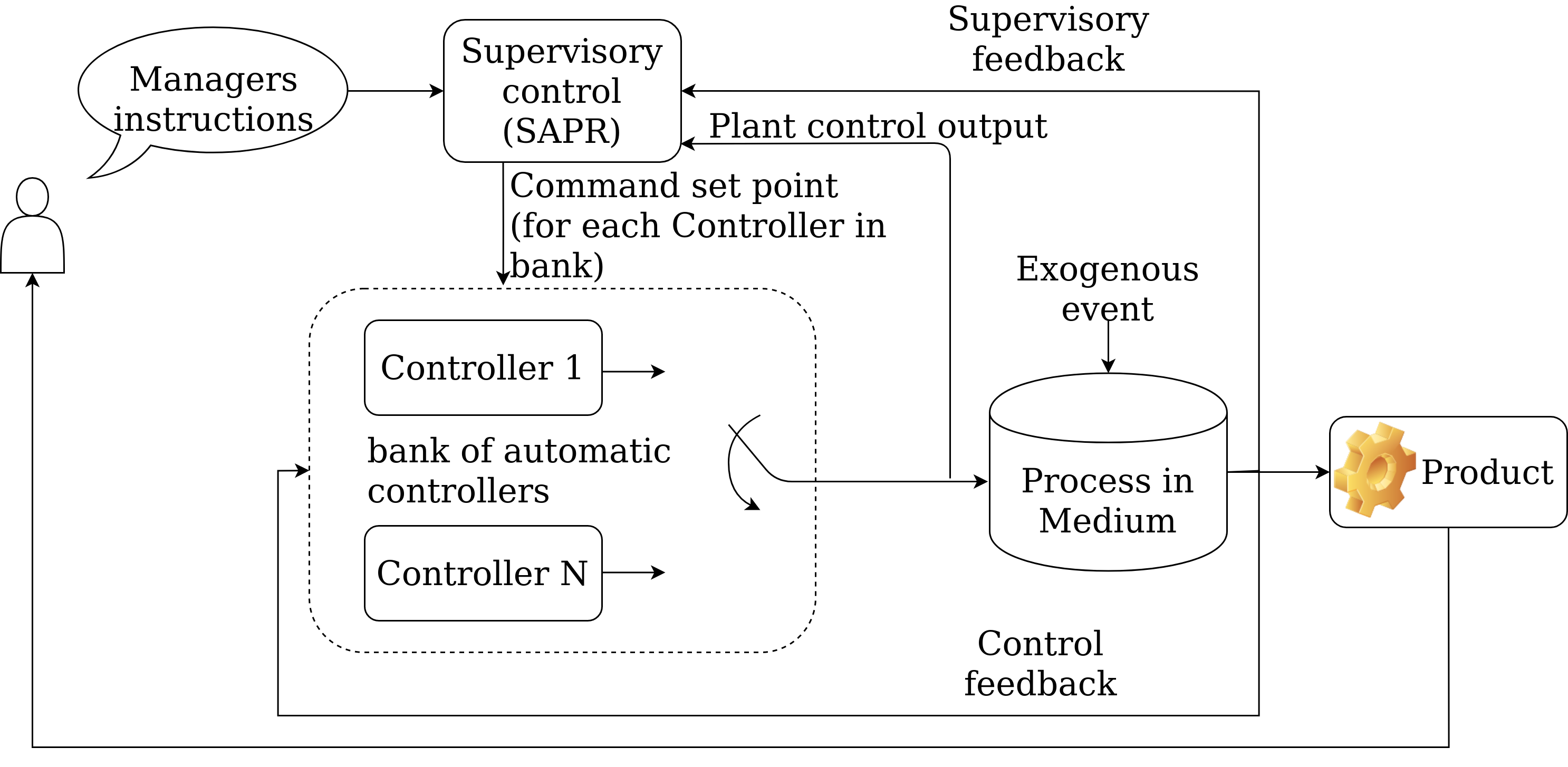
That leaves the last of the levels, which is partly in our area of responsibility. Level 2 - Supervisory Control (Figure 2.8). This level of control is higher than the automatic controllers of level 1 (which control only a small subsystem).
|
Fig. 2.8. Facilities control system from SCADA point of view (level 2). |
Decision-making control usually takes on the following functions:
- Sets control points for important process variables (depending on the nature of the product, volume and type of production) - it has a strong influence on process control, energy, quality and efficiency.
- Performance monitoring/diagnostics - checks sensors, actuators and process parameters for errors (results are saved).
- Start/stop/emergency - special discrete and continuous control models designed to respond to operator commands and diagnostic events (such as detected errors).
- Reconfiguration/settings monitoring - structural or parametric adjustment of the control loops. This is performed either in response to operator commands or in response to diagnostic events.
- Graphical interface - operator interface for manual operation and correction.
These systems are dependent on the type of controlled process (as opposed to Level 1, which is usually unified). Usually such systems are mix of hardware and software algorithms, and they are very expensive.
Consider CNC machine driver control system. Find out possible set points and describe functionalities according to level 2.
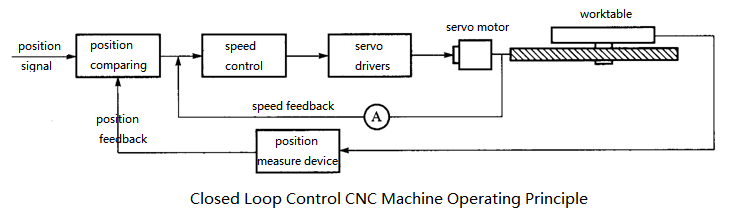
Fig. 2.9. Automatic control system of CNC motor driver (https://www.datancnc.com/index_projectxq_id_166_jpid_91.html). 2.6 Other control levels
Let us briefly consider the functions of Level 3 (production control):
- Process planning: availability of resources, their optimal use and processing.
- Maintenance management: the decision-making processes associated with the detection and deployment of complicated operations.
- Inventory management: decision-making processes related to the monitoring and deployment of raw materials, finished goods, etc.
- Quality management: assessment, documentation and quality management.
In the factory, this level is the responsibility of the chief technologist department and the quality control management (laboratories).
2.7. Conclusion
In this chapter we have considered the general features of the production management system. We have briefly described each of the levels and made basic diagrams.
The time and informativeness of the solutions increase as the level increases. At the lowest level, the control system is faster (one sensor) and at the higher levels - is slower (many sensors and processes). Over the management level, the information is aggregated over a certain period of time (days or week, maybe even slower). Each of describe levels is connected via a communication protocol (for low level this is CANBus, Fieldbus, etc. network), and all these communications forms a single SCADA system.
2.8 Section Tasks
- Draw the block diagram of a typical sensor.
- Draw the block diagram of a typical actuator.
- Consider the electro-hydraulic actuator of the valve. Examine and identify the actuator subsystems and describe it.
- Draw a block diagram of the level 1 of industrial control system.
- Consider a position control system with motor drive in CNC machine. Determine the main feedback encoders in the system. Identify the main sources of noises. What main differences between this system and conveyor drive system?
- Identify the main difference between the serial/logic control system and analogue control systems.
- Provide an example of industrial discrete sensors and industrial discrete actuators.
- State the three main functions of the supervisory control system.
- Describe the three main functions of the production control system.
- Examine and clarify specific activities to control production at any typical plant.
- Draw an automation pyramid and define levels.
3. Base characteristics of measurement systems
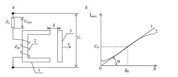
Fig. 3.1. Scheme (а) and static characteristics (b) of inductive sensor with parallel air gap: 1 - ideal (without loading) and 2 - real (with load).
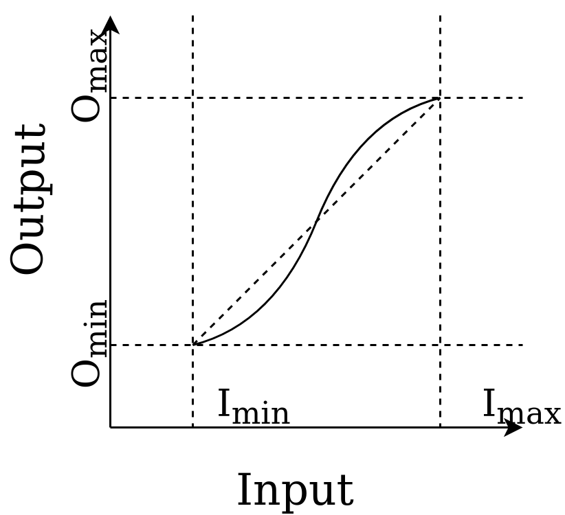
Fig. 3.2. Linearity of device.
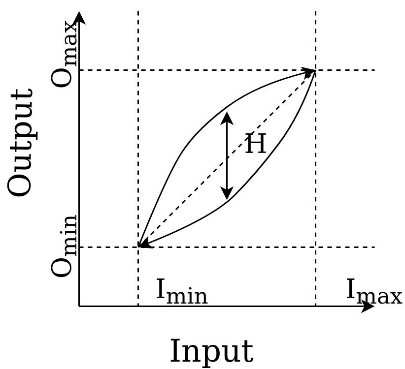
Fig. 3.3. Hysteresis of membrane manometer for equal pressure level (increase and decrease).
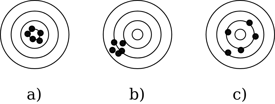
Fig. 3.4. Precision and accuracy (random and systematic errors).
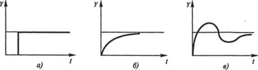
Fig. 3.5. Dynamic characteristics of sensor with step input. The descriptions of each case are showed below.
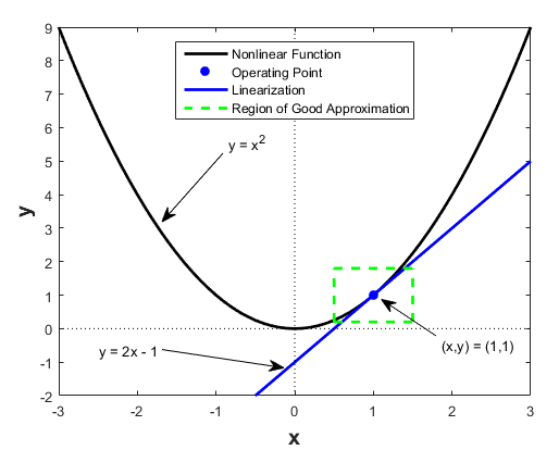
Fig. 3.6. Linearization in graphical phorm (https://kr.mathworks.com/help/slcontrol/ug/linearizing-nonlinear-models.html).
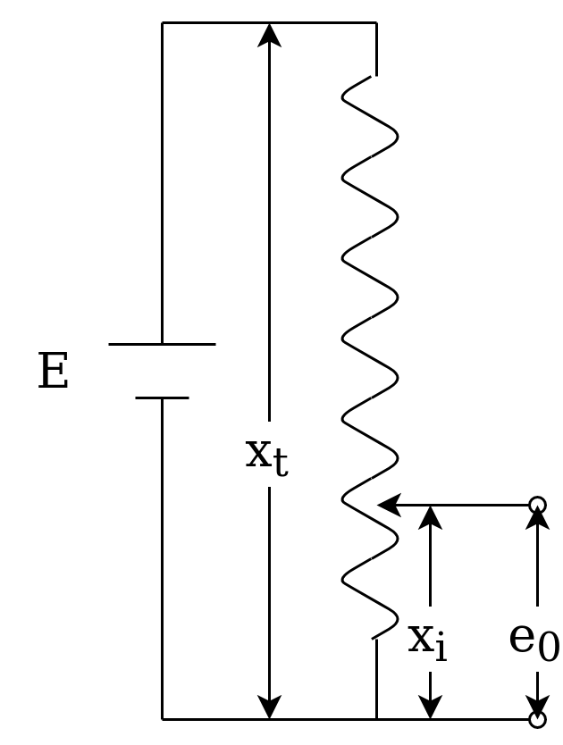
Fig. 3.7. Potentiometer.
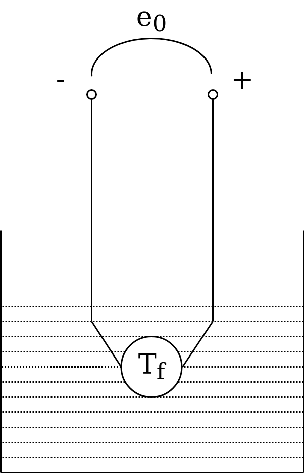
Fig. 3.8. Thermocouple.
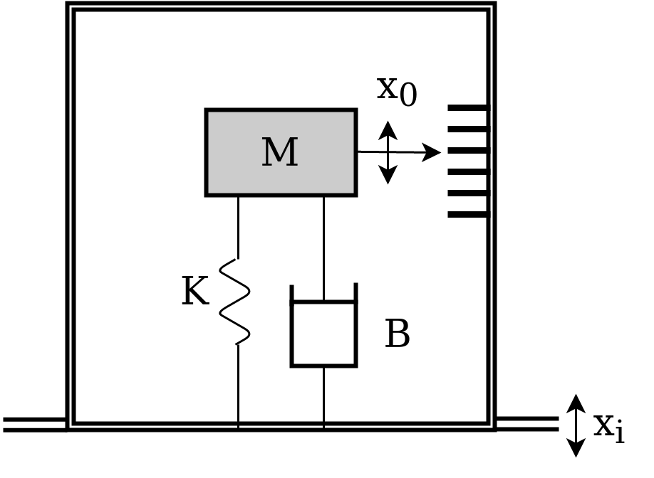
Fig. 3.9. Vibration sensor.

Fig. 3.10. Example of transient characteristics (https://en.wikipedia.org/wiki/Step_response).
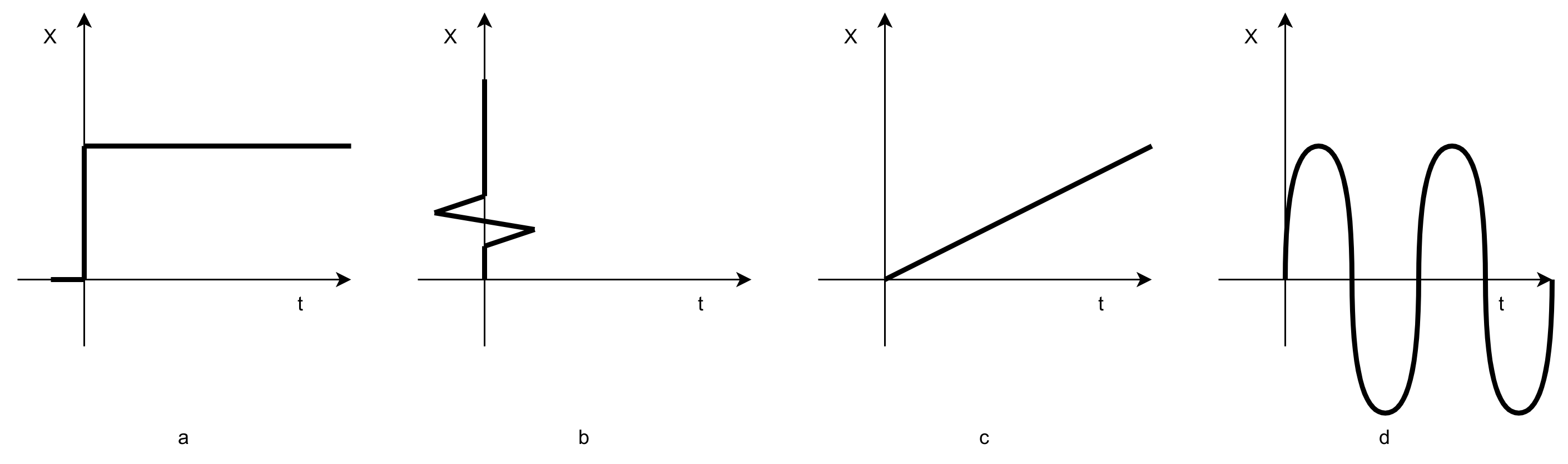
Fig. 3.11. Main type of input impact: a - single step, b - impulse (delta-function), c - linear, d - Sin (harmonic).
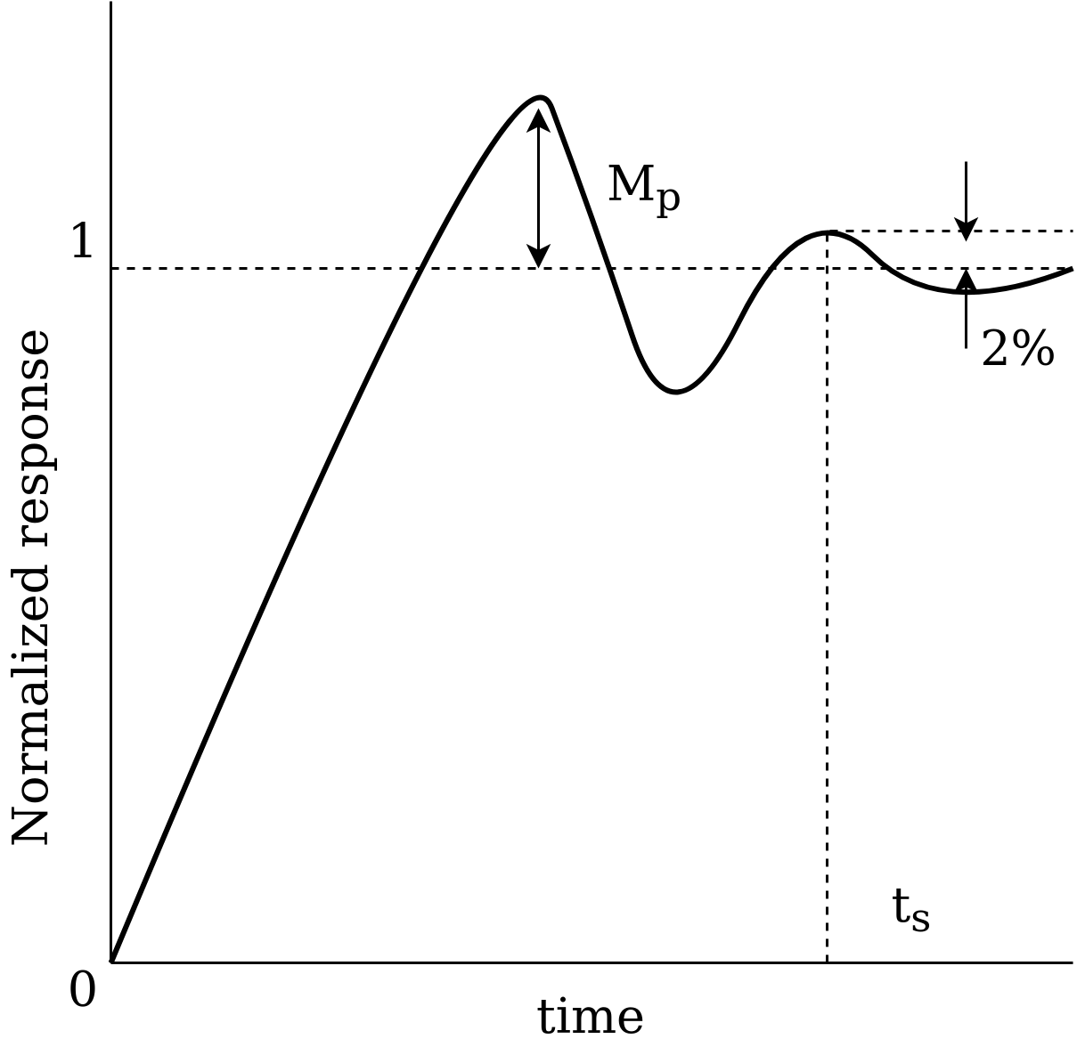
Fig. 3.12. Transfer function of dynamic system after step input (3.9 a).
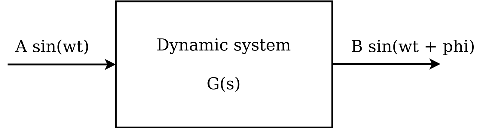
Fig. 3.13. Frequency answer
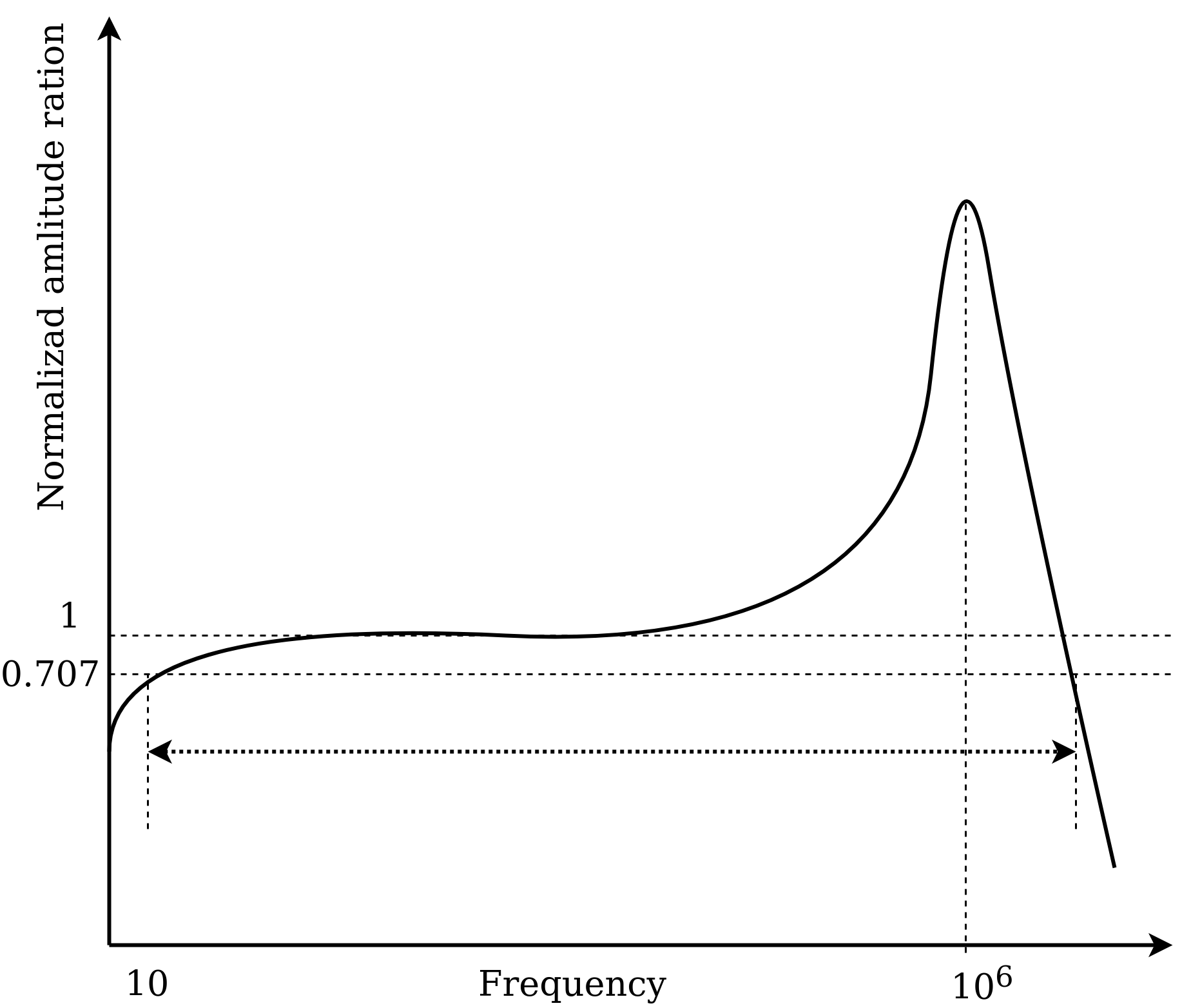
Fig. 3.14. Frequency-dependent amplitude characteristics for a piezoelectric accelerometer.
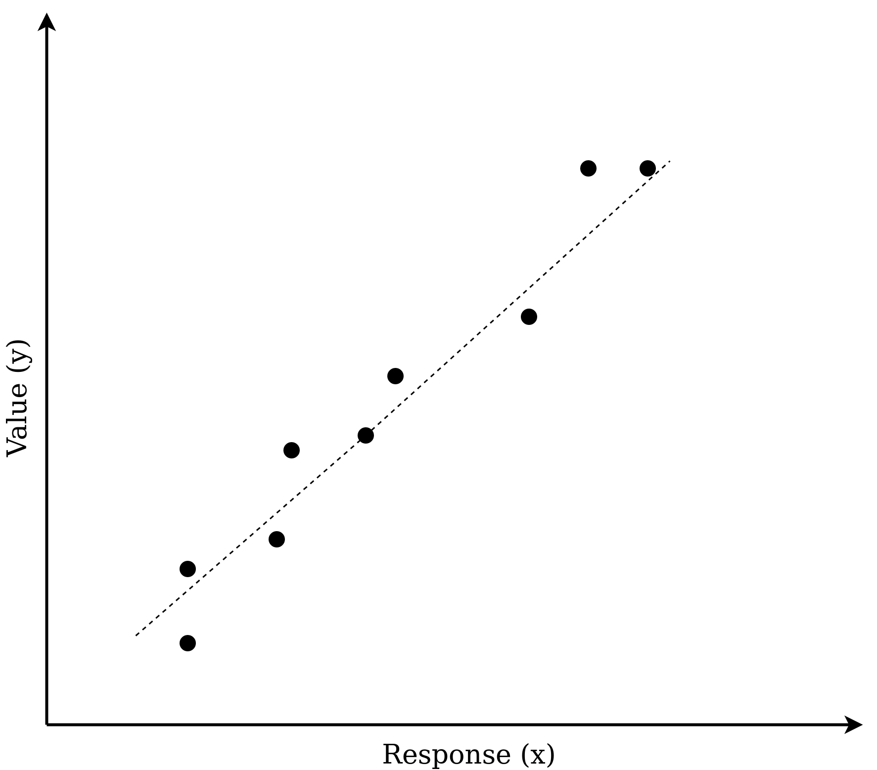
Fig. 3.15. Least square method.
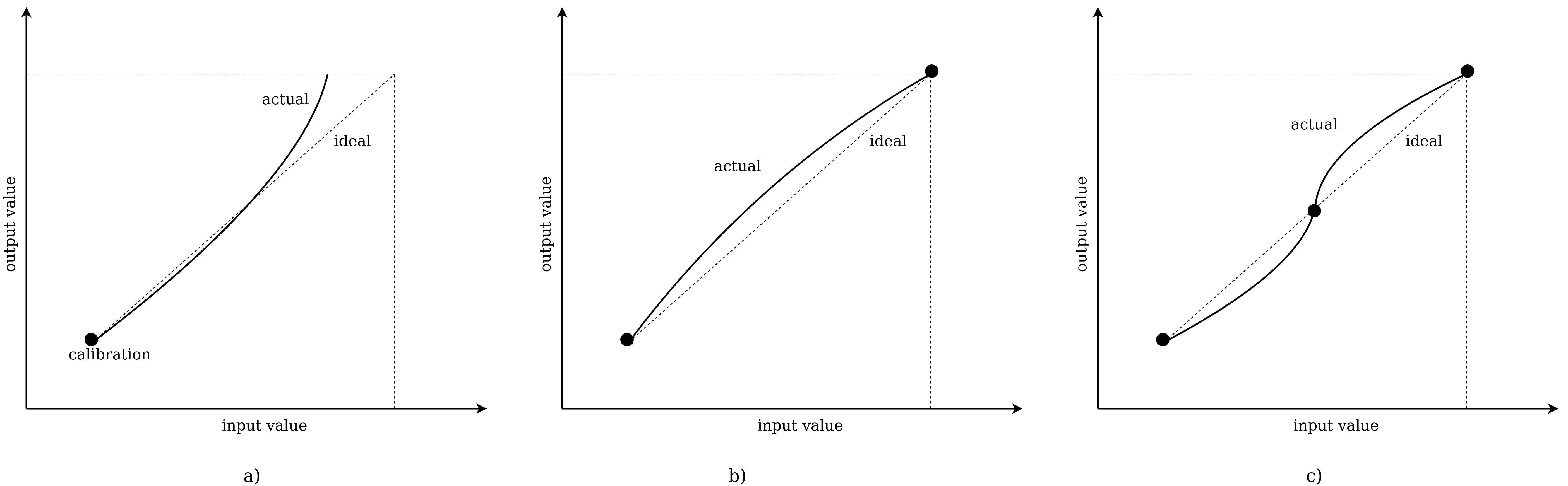
Fig. 3.16. Calibration with a) - one point, b) - two points, c) - three points. 4. Temperature measurement
5. Pressure and force measurement
6. Displacement and velocity measurement
7. Flow measurement
8. Level, humidity and pH measurement
9. Signal conditioning circuits
10. Conclusion
3. References
- Industrial Automation and Control course from NPTEL
- Instrumentation today
- IDC Technologies
- Measurement and Instrumentation. Theory and Application. Book. 2nd Edition • 2016
- Instrumentation Reference Book. Book. 4th Edition. 2010
- Caltech course CDS 101/110, Fall 2004, Analysis and Design of Feedback Systems
- Help in translate: Deepl.com
- Help with HTML table
- Perfect tools for construct diagrams: draw.io